8000MAX Series OTDR User Guide
De Gabrielle
December 31st, 2025
22 visualizações
Safety Warning
Power Adaptor
Input:
Output:
AC 100V ~ 240V, 50/60Hz; @1.6A
DC 12V, 3A ~ 4A
Use the power adaptor in strict accordance with the specifications, or it may cause damage to the device
Battery
Inside the unit is a dedicated lithium battery. For optimal battery performance, first use should be powered by the
internal battery. This will be exhausted, therefore, please ensure the first battery charge is no less than 4 hours. The
charging temperature range of the battery in the machine is -10oC ~ 50oC. When the ambient temperature is too high,
please terminate the charging for your safety. When the unit is idle for more than 2 months, it should be charged in
time to maintain the battery power. Do not take out the battery without permission; Please do not leave the battery
near a fire source or strong heat; Do not open or damage the battery; The temperature range of battery for long-term
storage is -20oC ~ 45oC.
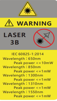
Laser Safety Instructions
The laser safety level of this unit is: CLASS III B, being potentially harmful to the human body, when in use, please pay
attention to safety. When the visible red light function of the unit is on, please do not look directly at the output port
of the red light source or at the end of the optical fibre connected to the red light output end, so as to avoid damage
to the eyes. When the unit is no longer in use, please cover the light outlet with a dust cap.
Product Features
1. Wavelength
Single mode: 1310/1550/1490/1625/1650
Multi mode:
850/1300
2. Measuring range: 120km~240km
3. Touch screen
Note: Different models with
different configuration
4. Data format: Sor format
5. Integration capabilities: Power meter, Light source, VFL, Insertion loss tester, OTDR, Event map, FDO
6. Keyboard input, edit save file name and line number
7. Supports user upgrade
8. The 5.6-inch TFT screen, 640*480 pixels, is visible in the outdoor sunlight
9. Two 7.4v /2500mAh x2 lithium batteries are used, which can be fully charged for more than 8 hours
10. Unit offers convenient screenshot interface function
User Guide
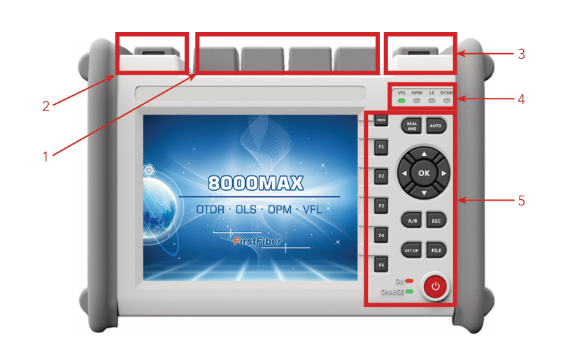
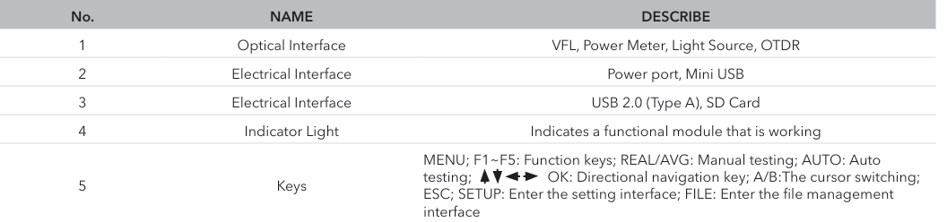
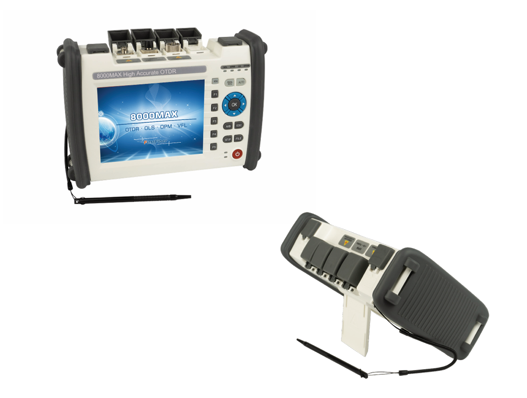
The 8000MAX series of the OTDR fibre optical testers offer multifunctional optical measurements, which integrates
OTDR, visual fault locator, optical power meter, light source, insertion loss tester and event map.
1.0 System Setting
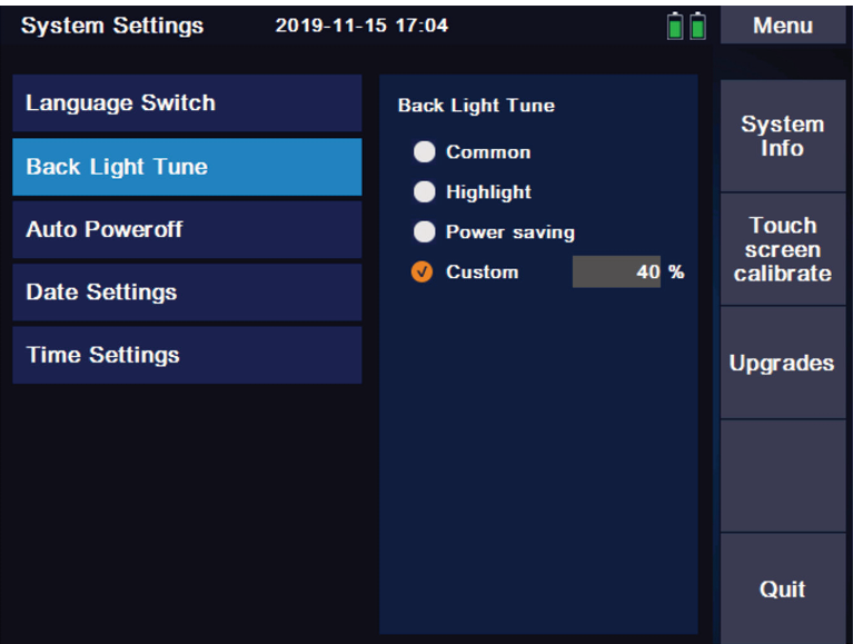
Press [F3] in the interface of main menu to enter the system setting interface, and the following settings can be
performed:
Language selection
Backlight adjustment
Automatic shutdown
Date Settings
Time Setting
Touch screen calibrate
Upgrades
System information (Series no, Unit model, Hardware and software version number)
2.0 OTDR Function Module
2.1 Setting
Under the main interface of the metre, press [SETUP] button to quickly enter the setting interface or press [F1] to enter
parameter setting on the main interface of OTDR.
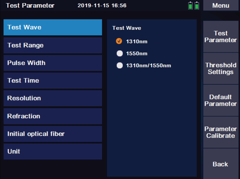
2.1.1 Test Parameter
Wavelength: 1310nm, 1550nm (Optional: 1625nm, 1650nm online test and 850nm/1300nm multimode)
Measuring range:
AUTO mode: The device will automatically set the most appropriate parameters for the current measurement, and the
measurement range and pulse width selected values cannot be modified at this time.
Manual mode: The range and pulse width can be set manually.
Pulse Width: Pulse width refers to the time width of emitting optical pulse signal during measurement. The wider
the pulse width is, the stronger the optical power injected into the fibre, the stronger the backscattering signal of the
f
ibre, the further the OTDR can effectively detect. The wide pulse width will cause saturation of the
initial reflection signal and could result in large blind areas. Please note, the selection of pulse width is related to the
measurement of fibre. The longer the length is, the wider the pulse width. It can only be modified in the automatic
measurement mode, which defaults to ‘automatic configuration’
Measuring time: In the mean measurement mode, the longer the detection time is, the better the signal-to-noise
ratio, the more accurate the test results are. The user should select the detection time, which is proportional to the
dynamic measurement.
Resolution: High resolution will have more sampling points and higher accuracy, but it will also increase the amount of
data collected.
Refractive index: Is the essential characteristics of optical fibre, which will differ between fibre optic manufacturers.
The refractive index is the key parameter to calculate the distance, which can not be arbitrarily set.
Unit: km/feet/miles
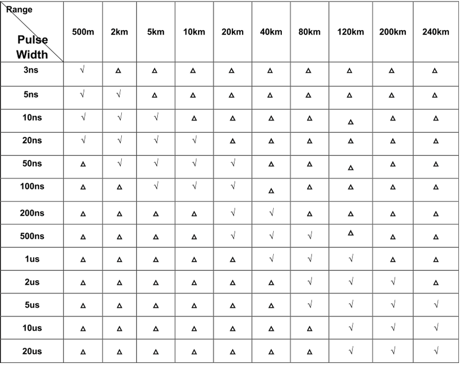
OTDR will automatically select the most appropriate reference pulse width when manual measurement range is set in
automatic mode.
The range and pulse width can be adjusted manually in manual mode. The following list is for reference only:
2.1.2 OTDR Parameter Setting
Various event measurement thresholds, including attenuation, reflection, slope, optical fibre end refractive index and
scattering coefficient settings.
The refractive index is selected by the user, and changing the refractive index setting will change the ranging result.
The refractive index is provided by the fibre optic cable or fibre optic manufacturer. Users are advised to calibrate the
group refractive index with a known length of fibre and record it.
The scattering coefficient is usually obtained from the fibre optic cable manufacturer
2.1.3 Restore to Default
Restore to factory default Settings.
2.2 Test
Optical Time Domain Reflectometer
Press [F1] key on the control panel to enter the measurement interface.
Following is the meaning of each label in the measurement interface:
Main menu
General section operation function menu
Parameter Settings
Measurement parameter Settings submenu
Curve operation
Curve manipulation sub-menu, including: cursor, zoom and curve translation
File operations
File operation submenu, including: open file, save file, multi trace operation and save file Settings.
Event analysis
Curve analysis sub-menu, including: cursor, curve zoom, event list view, add and delete events
More (multi-trace operation and event analysis function description)-
Add event: The event list is added accordingly- - - -
Delete events: The event list will delete the event accordingly
Clear choice: When multi-trace line loads, clear the selected curve and event list
Remove other: When multi-trace lines are loaded, clear the list of curves and events other than the selected
curve
Clear all: Clear all measurement curves and event lists in the current measurement interface
REAL TIME MODE:
Parameter settings->Test time->Average mode; press [REAL/AVG] key enter the real-time measurement mode. The
current circuit is measured in real time, and the measurement parameters cannot be modified in the measurement
mode. If the parameters need to be modified, the test needs to be stopped first. Event analysis will not be conducted
during the real-time test, and event analysis will only be conducted after the test is stopped
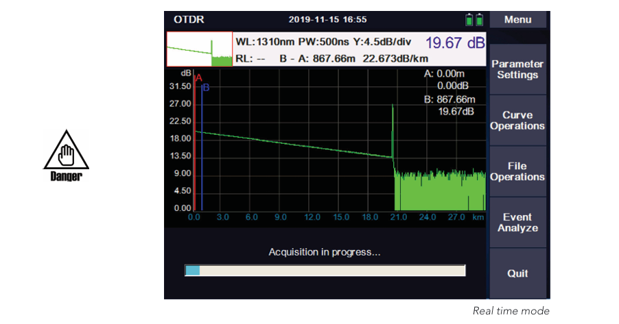
AVERAGE MODE
Real time mode
Parameter settings/Test time/XX seconds; Press [REAL/AVG] key enter the real-time measurement mode. The curve
consisting of the average values measured over a period of time can be displayed. The length of time can be edited
in the ‘measurement time’ option in [SETUP].
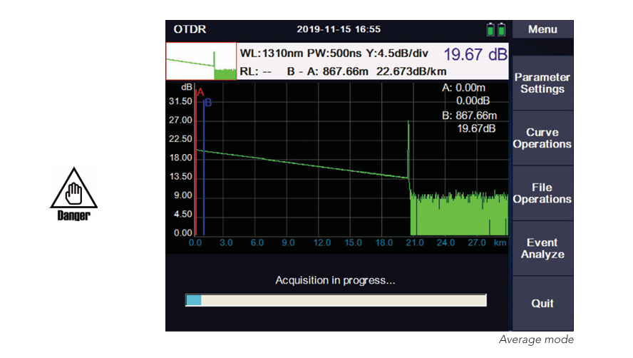
When the measurement is finished, the measurement result will be automatically saved.
Under no circumstances shall the optical interface and the end of the tail fibre connected to the optical interface be
directed to the eye of the operator or other person. Otherwise, the vision of the operator may be damaged, or even
blind
2.3 File Storage
Press [FILE] to view and edit stored files
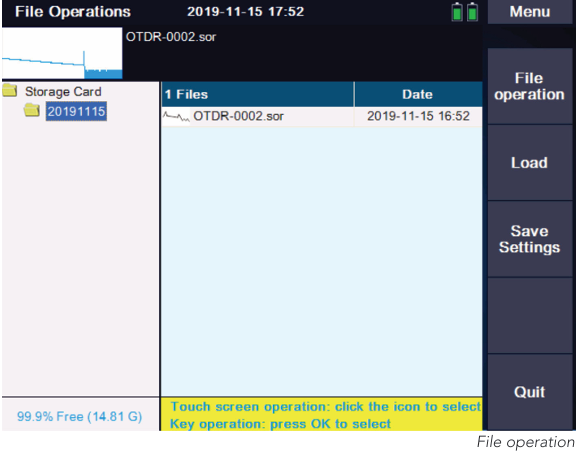
The menu provides a complete file storage, call out function. The results of each measurement are automatically
saved to internal storage (configurable) and marked with time, date, serial number and other information for easy
reference. Users can name, number, comment on each measurement curve, and generate complete reports.
2.4 Computer Software
If the user needs to carry out multi-curve comparison or other further analysis functions or remote operation, the
measurement data stored in the device after measurement can also be printed by software.
3.0 Other Functional Modules
3.1 VFL Module
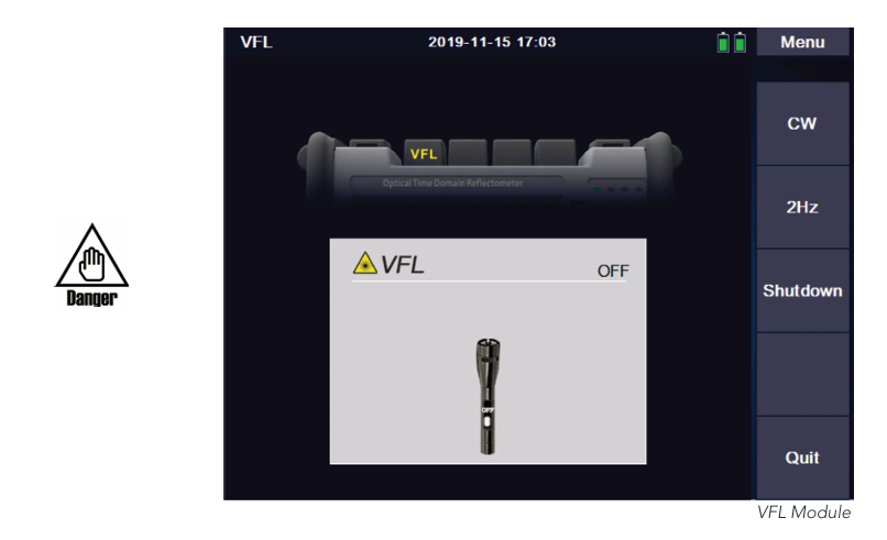
VFL module has two emission modes:
CW MODE: In this mode a continuous stream of visible light is emitted.
2Hz MODE: In this mode, visible light flashes at a frequency of 2Hz.
Press [Shutdown], [MENU] or [ESC] to turn off the VFL
VFL Module
When using the VFL module, do not aim the emitter at the eyes, otherwise it may cause irreversible damage to the
eyes.
3.2 OPM
Unit: dB, dBm, uW or mW
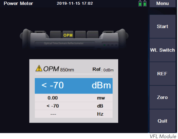
START/STOP
Turn on and off power metre function
Wavelength switching:
Press the “wavelength switch” TAB to switch the current wavelength
Set as the reference value:
Press the “REF” TAB to set the current value to the power metre reference
Clear zero:
Press the ‘Zero’ TAB to restore the reference value set
Frequency: The power metre has a frequency identification function and can identify 270Hz/1kHz/2kHz.c
3.3 Light Source
The light source module and OTDR use the same optical port. OTDR has several wavelengths (except for
multi-mode), and the light source has several wavelengths.
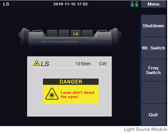
Start/Shutdown
Open and shutdown the light source module
WL Switch
Press“WL Switch”to change wavelength
Frequency switching
Press the “frequency switch” TAB to switch the output frequency of the laser: CW/270Hz/1kHz/2kHz
Description of function and index of light source:
1.The output power of the laser: -5dBm±2dB
2.Function on stable time rate: 3minutes
3.Short time stability: 0.05dB
4.Long time stability: 0.5dB
3.4 Loss Test Modules (Optional)
When the metre is installed with both the stable light source module and the power metre module, the loss test
module will be automatically activated.
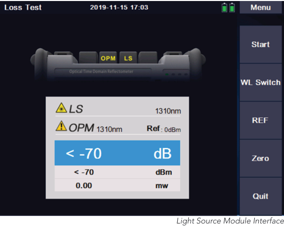
Start/stop: Turn on and off the loss test module
WL Switch: Press the ‘WL Switch’ TAB to switch the current wavelength
REF: Set the reference value.
Zero: Restore the set reference value
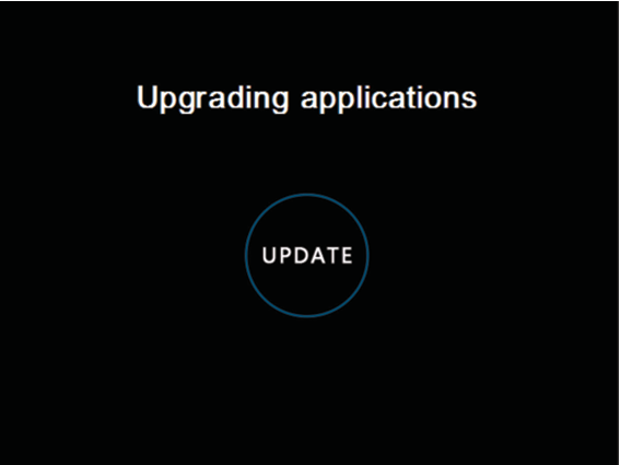
4.0 Software Upgrade
Firmware updates are made by plugging a USB drive into the USB port (the upgrade software must be in the root
directory).
Steps:
1. Place the software upgrade package in the root directory of your USB flash drive.
2. Turn on the unit and insert the U disk into the USB port of the unit.
3. The main interface-->System Settings-->Software upgrade
4. After entering the upgrade interface, the upgrade will be completed automatically
Note: during the upgrade, please do not cut off the power or unplug the USB drive. These illegal operations may
cause system software damage and the metre cannot start normally. Once this happens, you must contact the
manufacturer or the authorized after-sales service point of the manufacturer for system repair.
5.0 Instrument Maintenance and Trouble Shooting
5.1 Cleaning of connectors
The optical output interface of this series of fibre optic tester is a universal, replaceable interface. In case the tester
fails to test the normal curve, or the test result is not accurate, consider cleaning the connector first.
When cleaning, be sure to do it when the OTDR function and visual red light fault location function are turned off.
Unscrew the output port and wipe the end face with a special clean paper towel or cotton swab moistened with
alcohol. At the same time, please cover the dust cap after the use of the unit, and keep it clean.
5.2 Instrument screen cleaning
The display of this series of fibre optic comprehensive tester is a 5.6-inch TFT color LCD with touch screen. Do not
click the LCD screen with sharp objects when using, otherwise the LCD screen may be damaged: when cleaning, wipe
the LCD screen with soft paper. Do not use organic solvent to wipe the LCD screen, otherwise it may cause damage to
the LCD screen.
5.3 Calibration
It is recommended to calibrate the fibre optic tester every two years. For specific calibration, please contact the unit
supplier
6.0 Common Faults and Treatment Methods
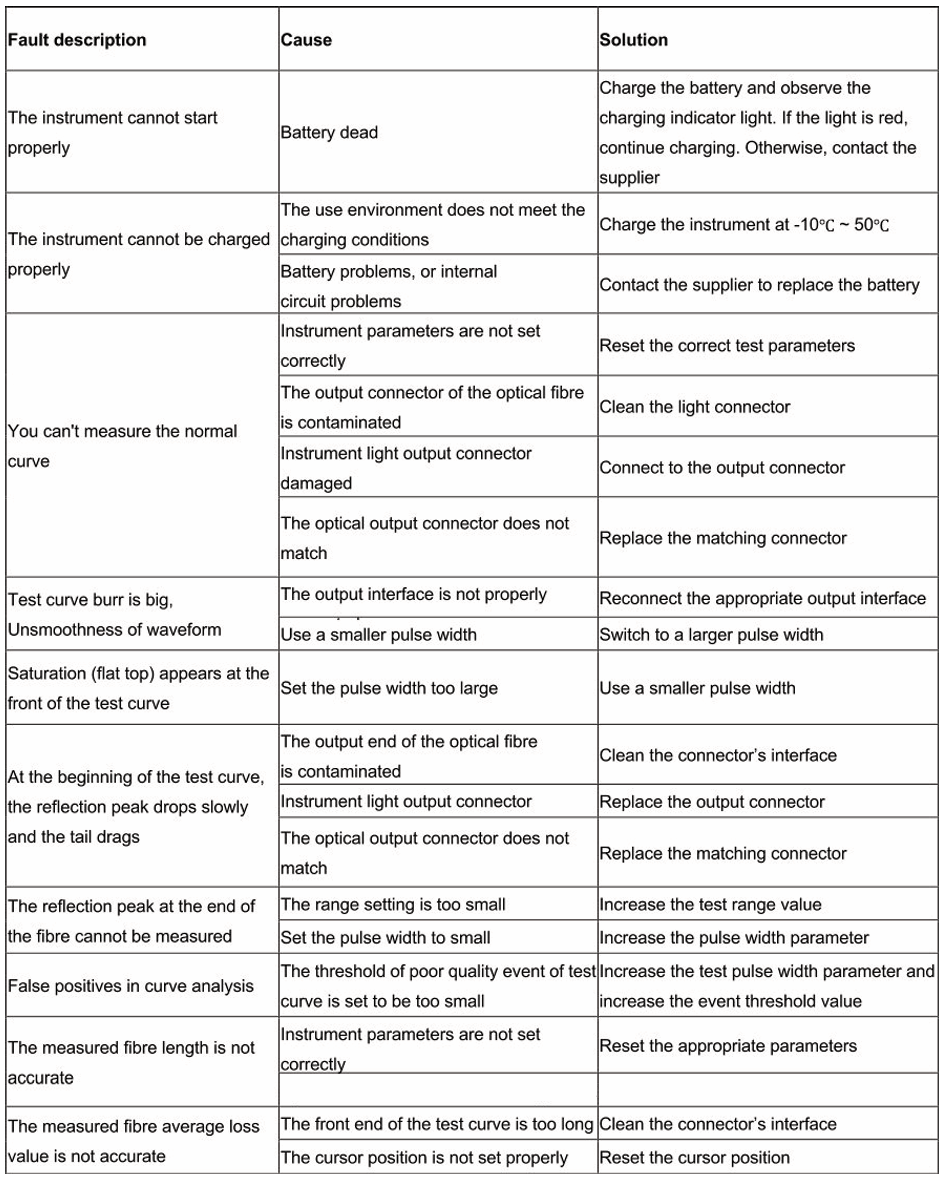
Note: The above description is for reference only. Please refer to the new instructions for detailed usage.
During the use of the unit, if there is any question, please contact with the unit supplier.
In the use of the unit, without permission, users are strictly prohibited to dismantle the machine,
otherwise will lose the warranty qualification.
Anteriro
FC1500 User Guide
Leia mais
Próxima
980TEKOTDR User Guide
Leia mais


